Main Module:
module counter_16bit (q_out,co,count,clk,clr,value,load);
output co;
output [16:0] q_out;
input clk,clr,count,load;
input [16:0] value;
reg [16:0] q_out;
assign co = count & (q_out==16'd65535);
always @ (posedge clk)
begin
if(~clr)
begin
q_out<=16'b0000000000000000;
end
else if(load)
begin
q_out<= value;
end
else if (count)
begin
q_out<=q_out+1'b1;
end
else
begin
q_out<=q_out;
end
end
endmodule
Stimulus:
module stimulus;
wire co;
wire[16:0] q_out;
reg clk,clr,count,load;
reg [16:0] value;
counter_16bit Cntr0 (q_out,co,count,clk,clr,value,load);
initial
begin
clk=1'b0;
forever
#1 clk =~clk;
end
initial
begin
clr=0;
count=1;
load=0;
value=16'd65535;
#5 clr=1;count=1;load=1;value=16'd65535;
#40 clr=1;count=1;load=0;value=16'd65535;
#10 clr=0; count=0;load=0;value=16'd65535;
#10 $stop;
#10 $finish;
end
endmodule
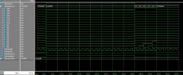
Waveform:

4- bit Counter waveform:

Asynchronous Up-Down 8-bit Counter.
Main Module:
module counter_8bit (q_out, co, count, clk, clr, updn);
output co;
output [7:0] q_out;
input clk, clr, count;
reg [7:0] q_out;
input [7:0] updn;
assign co = count & (out==8'b11111111);
always@(posedge clk)
begin
if(~clr)
begin
out <= 4'b00000000;
end
else if (count)
begin
if(updn)
begin q_out <= q_out + 1'b1;
end
else
begin q_out <= q_out - 1'b1;
end
end
else
begin
q_out <= q_out;
end end
endmodule
stimulus :
module Stimulus;
wire [7:0] q_out;
wire co;
reg clk, clr, count;
reg [7:0] updn;
counter_8bit cntr (q_out, co, count, clk, clr,updn);
initial
begin
clk=1'b0;
forever
#1 clk = ~clk;
end
initial
begin
clr = 0; count = 1;
#10 clr = 1; count = 1; updn=0;
#10 clr = 1; count = 1; updn=1;
#10 clr = 1; count = 0; updn=0;
#10 clr = 1; count = 0; updn=1;
#10 clr = 0; count = 1;
#10 $stop;
#10 $finish;
end
endmodule
Waveform is given below:

Keyboard Interfacing with FPGA
Top Module
module top_keyboard(out,kbrd_clk,kbrd_data,rst);
input kbrd_clk,kbrd_data,rst;
output [3:0]out;
wire [7:0] data;
deserialize des(.in(kbrd_data),.clk(kbrd_clk),.out(data),.rst(rst));
decoder dec(.out(out),.in(data));
endmodule
Deserialize Module
module deserialize(in,clk,out,ready,rst);
input in,clk,rst;
output [7:0] out;
output ready;
reg start_bit,r0,r1,r2,r3,r4,r5,r6,r7,parity,stop;
reg [3:0]counter;
reg ready;
reg [7:0] out;
always@(negedge clk or negedge rst)
begin
if(!rst)
begin
start_bit <= 0;
r0<= 0;
r1<= 0;
r2<= 0;
r3<= 0;
r4<= 0;
r5<= 0;
r6<= 0;
r7<= 0;
parity<= 0;
stop<= 0;
end
else
begin
stop <= in;
parity <= stop;
r7 <= parity;
r6 <= r7;
r5 <= r6;
r4 <= r5;
r3 <= r4;
r2 <= r3;
r1 <= r2;
r0 <= r1;
//start_bit <= r0;
end
end
always@(negedge clk or negedge rst)
begin
if(!rst)
begin counter <= 0; ready <= 0; end
else if(counter == 4'd10)
begin counter <= 0; ready <= 1; end
else
begin counter <= counter + 1; ready <= 0; end
end
always@(posedge clk)
begin
if(ready)
out <= {r7,r6,r5,r4,r3,r2,r1,r0};
else
out <= out;
end
endmodule
Decoder Module
module decoder(out,in);
output [3:0] out;
input [7:0]in;
reg [3:0] out;
always@(in)
begin
case(in)
8'h16: out <= 4'd1;
8'h1E: out <= 4'd2;
8'h26: out <= 4'd3;
8'h25: out <= 4'd4;
8'h2E: out <= 4'd5;
8'h36: out <= 4'd6;
8'h3D: out <= 4'd7;
8'h3E: out <= 4'd8;
8'h46: out <= 4'd9;
8'h45: out <= 4'd0;
default : out<= 4'd0;
endcase
end
endmodule
RTL
Implementation on Virtex 2 Pro Board
NET "kbrd_clk" LOC = "AG2" ;
NET "kbrd_data" LOC = "AG1" ;
NET "out[0]" LOC = "AC4" ;
NET "out[1]" LOC = "AC3" ;
NET "out[2]" LOC = "AA6" ;
NET "out[3]" LOC = "AA5" ;
NET "rst" LOC = "AC11" ;
We implement it on Virtex 2 Pro Board and use four LEDs for displaying results.


