State space model:
State space model of this system is defined as we consider two state variables ball position ‘r’ and velocity
Code s = tf('s');P_ball = -m*g*d/L/(J/R^2+m)/s^2H = -m*g/(J/(R^2)+m);
A = [0 1 0 0
0 0 H 0
0 0 0 1
0 0 0 0];
B = [0 0 0 1]';
C = [1 0 0 0];
D = [0];
ball_ss = ss(A,B,C,D)
System response using Matlab Command:
In this section we will check the transfer function,system response at step input and then plot them to check stability.we see that our system is not stable so first we stable it then design PID controller in order to improve the response of our system as efficient as possible.
Stability:Response of this system was open loop so by giving unity gain feedback our system becomes stable. Code sys_cl=feedback(C*P_ball,1);
Designing of PID controller:
We design PID using Ziegler Nichols method. Transfer function of PID is given below
C(s)=Kp +KI/s+Kds
=Kp(1+1/T1s+Tds)
Parallel Form of the PID
where: Kp := Proportional Gain KI := Integral Gain TI := Reset Time =Kp/Ki Kd :=Derivative gain Td := Rate time or derivative time
The proportional term in the controller generally helps in establishing system stability and improving the transient response while the derivative term is often used when it is necessary to improve the closed loop response speed even further. Conceptually the effect of the derivative term is to feed information on the rate of change of the measured variable into the controller action. The most important term in the controller is the integrator term that introduces a pole at s = 0 in the forward loop of the process.The proportional term in the controller generally helps in establishing system stability and improving the transient response while the derivative term is often used when it is necessary to improve the closed loop response speed even further. Conceptually the effect of the derivative term is to feed information on the rate of change of the measured variable into the controller action. The most important term in the controller is the integrator term that introduces a pole at s = 0 in the forward loop of the process.
Steps to determine PID controller parameters:
1. Reduce the integrator and derivative gains to 0.
2. Increase Kp from 0 to some critical value Kp=Kc at which sustained oscillations occur.we achieve such ocilations at KP=1.then check step response
3. Note the value Kc and the corresponding period of sustained oscillations
In this system we apply KP=1 we get ocillations then change then increase KP=10 and introduce Kd=10 for the removal of overshoot and then check response we found that over shoot reduces but not at desired level
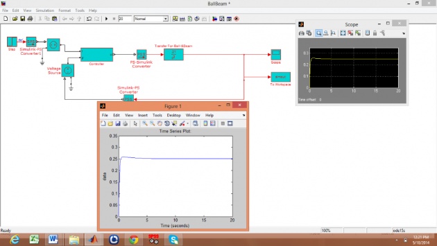
Simulink
Block Diagram of Ball and Beam System

Output of Ball and Beam System
References
http://www.purduecal.edu/cpmi/NSF%20Courses/ECET-462/LABORATORIES/8-TuningofaPIDcontrollerusingZiegler-NicholsMethod.pdf
http://www.s2is.org/Issues/v5/n1/papers/paper2.pdf
Values of Kp Kd Ki (R,C):
Kp = 10
Rf = 1K
Ri = 10K
Kd = 10
R = 100K
C = 100 micro Farad


