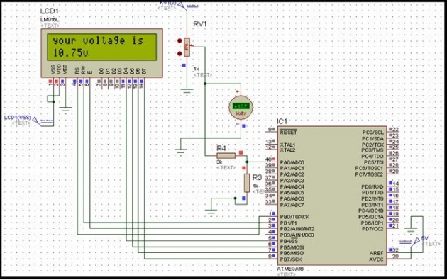
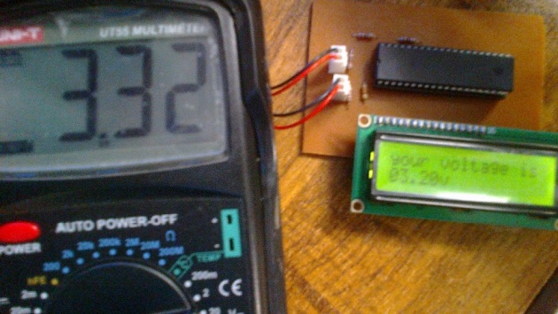
In this Blog I will share with you Digital Voltmeter Coding and Its Running Simulation.
Simulation:

PROGRAMCODE:
#define F_CPU 1000000
#include<avr\io.h>
#include<avr\interrupt.h>
#include <util/delay.h>
/////////////// Macros Definition/////////////////
#define Bit(x) (0x01 << (x))
#define BitSet(p, m) ((p) |= (m))
#define BitClr(p, m) ((p) &= ~(m))
unsigned int x,vin,temp;
unsigned char d1,d2,d3,d4,i,temp2;
unsigned char msg1[]="your voltage is";
void LCDcmd(unsigned char cmdout)
{
PORTB= cmdout;
BitClr(PORTB, Bit(0)); //Clear RS
BitClr(PORTB, Bit(1)); //Clear RW
BitSet(PORTB, Bit(2)); //Set Enable
_delay_us(100);
BitClr(PORTB, Bit(2)); //Clear Enable
}
void cmd_4b(unsigned char Cmd)
{
char Cmd1;
Cmd1 = Cmd & 0xF0; //mask lower nibble because PA4-PA7 pins are used
LCDcmd(Cmd1); // send to LCD
Cmd = Cmd << 4; //shift left 4 bits
LCDcmd(Cmd);
}
void LCDdata(unsigned char dataout)
{
PORTB = dataout;
BitSet(PORTB, Bit(0)); //Set RS
BitClr(PORTB, Bit(1)); //Clear RW
BitSet(PORTB, Bit(2)); //Set Enable
_delay_us(50);
BitClr(PORTB, Bit(2)); //Clear Enable
}
void data_4b(unsigned char data_value)
{
char data_value1;
data_value1 = data_value & 0xF0;
LCDdata(data_value1);
data_value1 = data_value << 4;
LCDdata(data_value1);
}
void LCD_init() // Initialize LCD
{
cmd_4b(0x02); //to initialize LCD in 4-bit mode.
cmd_4b(0x28); //to initialize LCD in 2 lines, 5x7 dots and 4bit mode
cmd_4b(0x0C); //Display is ON, cursor OFF
}
void InitADC(void)
ISR(ADC_vect)
{
PORTB = ADCH;
x=ADC;
vin=(x)*(1.956);
d1=(vin/1000);
temp=vin%1000;
d2=temp/100;
temp2=temp%100;
d3=temp2/10;
d4=temp2%10;
d1=d1 |0x30;
d2=d2 |0x30;
d3=d3 |0x30;
d4=d4 |0x30;
cmd_4b(0xC0);
_delay_ms(500);
data_4b(d1);
data_4b(d2);
data_4b('.');
data_4b(d3);
data_4b(d4);
data_4b('v');
BitSet(ADCSRA, Bit(6)); //Start conversion again
}
int main(void)
{
DDRA = 0x00; //PortA as input for ADC input
DDRD = 0xFF; //PortD as output for lower byte of Digital value
DDRB = 0xFF; //PortB as output for higher byte of Digital value
LCD_init();
cmd_4b(0x01);
cmd_4b(0x80);
_delay_ms(50);
for(i=0;msg1[i];i++)
{
data_4b(msg1[i]);
_delay_ms(50);
}
InitADC();
sei();
while(1);
}
void InitADC(void)
{
BitClr(ADMUX, Bit(7)); //Internal 2.56V selected as Vref
BitSet(ADMUX, Bit(6)); //Internal 2.56V selected as Vref
BitClr(ADMUX, Bit(5)); //Right adjusted result
BitClr(ADMUX, Bit(4)); //Single ended (Gnd as common ground)
BitClr(ADMUX, Bit(3)); //non-differential input on ADC0 channel i.e. PA0, Pin No. 40
BitClr(ADMUX, Bit(2)); //
BitClr(ADMUX, Bit(1)); //
BitClr(ADMUX, Bit(0)); //
//ADMUX = 0xC0; //Same settings as given above
BitSet(ADCSRA, Bit(7)); //Enable ADC
BitClr(ADCSRA, Bit(5)); //Disable Auto Trigger
BitSet(ADCSRA, Bit(3)); //Enable ADC Interrupt
BitSet(ADCSRA, Bit(2)); //Prescaler = Fosc/128
BitSet(ADCSRA, Bit(1)); //Prescaler = Fosc/128
BitSet(ADCSRA, Bit(0)); //Prescaler = Fosc/128
//ADCSRA = 0x8F ; //Same settings as described above
BitSet(ADCSRA, Bit(6)); //Start Conversion
}
Practically taken picture of Digital Voltmeter project in working by using above code.


