Front Panel of a Calculator 
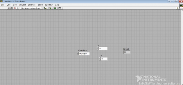
I made a project of Calculator in “LAB View 8.6” by opening the “.vi file”. On the “front panel” I put the two “Numeric control” and named it x and y. And also draw the “Numeric Indicator” named it result. After this I put the “enum” in order to add at least 10 different functions and named it “Calculator”.
I added the following Operations to my “CALCULATOR”:
1- Adder
2- Square of x
3- Multiply
4- Square root
5- Divide
6- Subtract
7- Increment
8- Decrement
9- Negative of Number
10- Reciprocal
Adder:
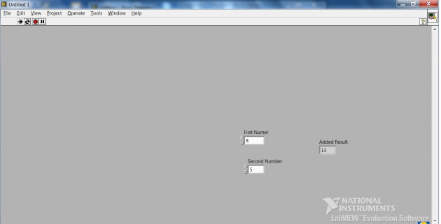
I opened the “.vi file” of” lab view” and right clicked on the “front panel” and select the “numeric control” and put on the screen of the “front panel” named it First number. I repeat the process for the second value and named it second number. After this step I select the “numeric indicator”, modern option by right clicking on the screen of “front panel” and named it “Added Result” as showed in the below diagram.
Here is Front Panel of Adder:

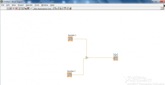
After the above steps I moved to the “Block diagram” and select the “adder sign” from mathematics option by right clicking on the screen of the “Block diagram” and wired it with the two “Numeric controls” and one “Numeric Indicator”. Then I run the project and the result showed with our require values as showed in the above “front panel” figure.
Here is a Block Diagram of Adder:
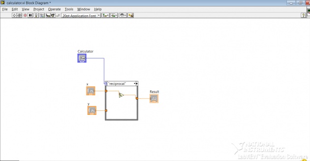
After all these steps I moved to the “Block Diagram” to insert the “Adder sign” and wired it with the both “numeric control” and “numeric indicator”. Then I select the “case structure” from program and put on by selecting the inner wires and right clicked on the “case structure” blank space and click on the add case for every value so that I can add all 10 functions to that “case structure” and can wired them easily. I also wired up the ”enum” with “case structure” and at the end I put a “for loop” on whole circuit to enable it run continuously. I run the project successfully and outputs of our desire value came out .
Block Diagram


