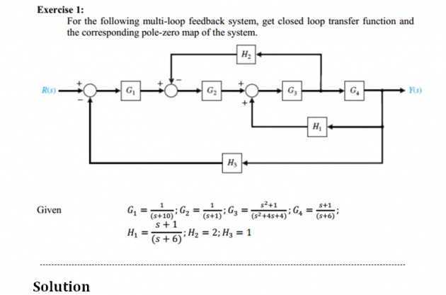
First of all simplify the diagram
- Move the G3 to the left past of summing junction
- We get G2 and G3 in series and H1 and G3 in series
- Solve the above cascaded form
- Let A = G2.G3 &B = H1.G3
- Now H2 forms feedback for Aand B forms feedback for G4
- Solving above
- C = A+H2 &D = G4/(1+B.G4)
- Now G1 , C & D are in series so
- E = G1.C.D
- Now , H3 forms feedback for E so ,
- SYS = E/(1+E.H3)
CODING
n1 = [0 1];
d1 = [1 10];
G1 = tf(n1,d1);
n2 = [0 1];
d2 = [1 1];
G2 = tf(n2,d2);
n3 = [1 0 1];
d3 = [1 4 4];
G3 = tf(n3,d3);
n4 = [1 1];
d4 = [1 6];
G4 = tf(n4,d4);
n5 = [1 1];
d5 = [1 6];
H1 = tf(n5,d5);
H2 = 2;
H3 = 1;
A = series(G2,G3);
B = series(H1,G3);
C = feedback(A,H2);
D = feedback(G4,B,1); %% +ve feedback
E = series(G1,C)
F = series(E,D);
SYS = feedback(F,H3)
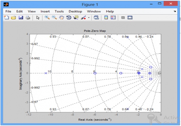
pzmap(SYS)
gridon
OUTPUT
SYS =
s^6 + 11 s^5 + 39 s^4 + 63 s^3 + 62 s^2 + 52 s + 24
----------------------------------------------------------------
14 s^7 + 325 s^6 + 2755 s^5 + 11324 s^4 + 25550 s^3 + 32716 s^2 + 23750 s + 8604
-------------------------------------------------------------------------------------------------------------------------------
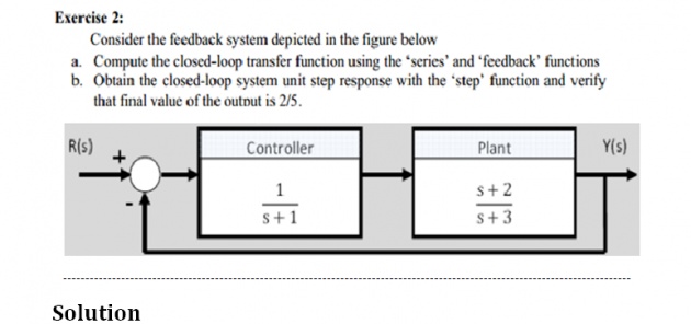
- First solve cascaded portion
- Then solve the feed back portion
- Ant the end use the step function to find the step response of system
CODING
n1 = [0 1];
d1 = [1 1];
controller = tf(n1,d1);
n2 = [1 2];
d2 = [1 3];
plant = tf(n2,d2);
S = series(controller,plant);
SYS = feedback(S,1)
step(SYS)
gridon
OUTPUT
SYS =
s + 2
-------------
s^2 + 5 s + 5
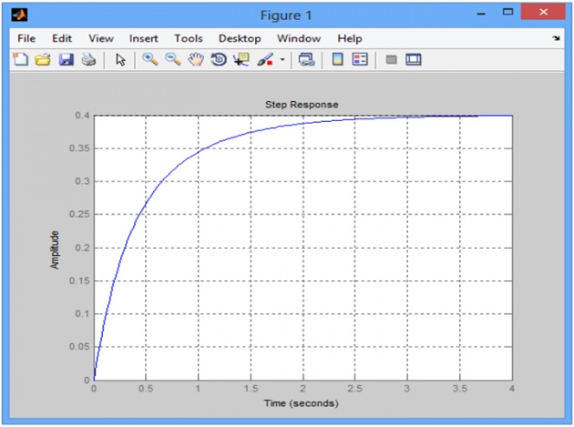
Graph shows that output is
Output = 0.4 = 2/5
-------------------------------------------------------------------------------------------------------------------------------
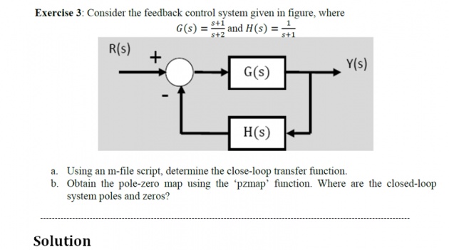
- First solve feedback portion
- Then find its pole _zero map
CODING
n1 = [1 1];
d1 = [1 2];
G =tf(n1,d1);
n2 = [0 1];
d2 = [1 1];
H = tf(n2,d2);
SYS = feedback(G,H)
Poles_of_SYS = pole(SYS)
Zeros_of_SYS = zero(SYS)
pzmap(SYS)
gridon
OUTPUT
SYS =
s^2 + 2 s + 1
-------------
s^2 + 4 s + 3
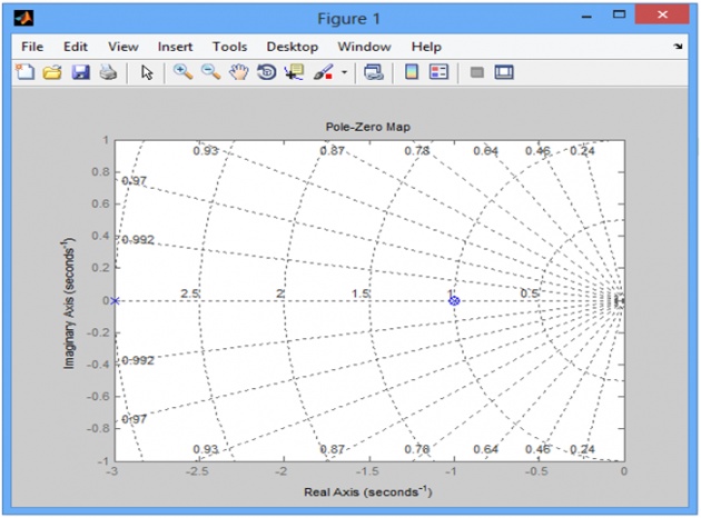
Poles_of_SYS =
-3
-1
Zeros_of_SYS =
-1
-1
