MAKING OF AUDIO LED VOLUME METER USING “LAB VIEW”
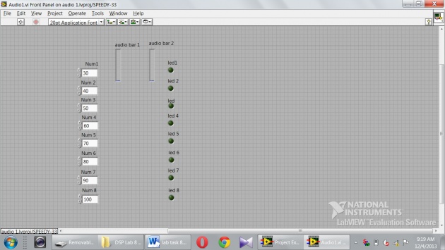
“Front Look”
First of all I get 8 “numeric controls” and placed on the “front panel” of the project by selecting “speedy 33 kit” while opening the new project at the start. Then I also selected the 8 “LEDs” and placed them on the “front panel” for for showing the audio volume meter result, thus for clear and accurate result I also placed two “audio bar” named audio bar 1 and audio bar 2. Similarly I also named “control bar” and “LEDs” from Num1 to Num 8 and led1 to led8 respectively.
First result (Gain):

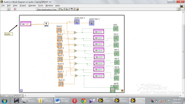
Then I moved to the “block diagram” and selected the audio input and placed on the left top corner and labeled it by arrow “Audio input”. Then I selected the “RMS sign” and placed it near the “audio input”. After that I selected the 8 “greater than” sign (>) and 8 “LEDs” and connected them parallel by wiring. With these I also connect the “front panel LEDs” for showing the result on front panel. Then I connected the two terminals of the greater then (>) sign one with the value coming out from “RMS” and the second with “numeric value”. I also wired the two “audio bar” with the value coming out from “RMS”. At the end I get the “while loop” and apply on the whole “project” circuit by selecting all.
We used the “speedy 33 kit” and tested the result was achieved and we have the following images of the lab performance.
Noted that I used the “Numeric control”, so that the user can use values with his/her own wish.
“Block FIGURE”

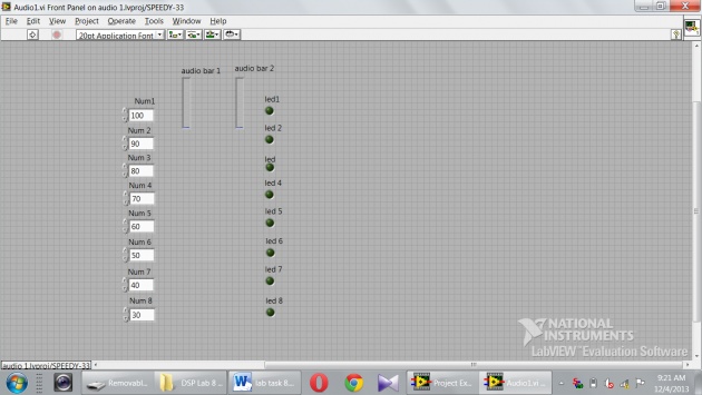
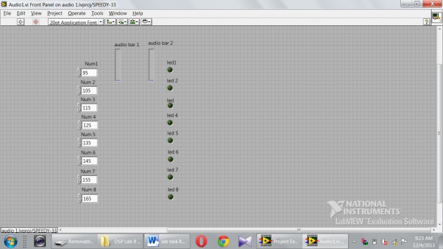
Similarly I change the value of “Gain” of audio signal in the “Num1-Num8” also called “Numeric control, because user can use the values in these boxes with his/her wish to bring the different results and then to show them on the “LEDs” of “front Panel”.
Another Results of the volume meter by changing the gains :

It is very useful task, which I done using “LAB VIEW” to know about the concept of MP3 players, audio signal, radio tuning, guitar sound tuning or TV channels responses.
writer: Amar Annex


