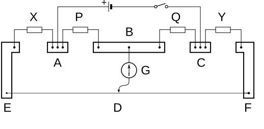
Carey Foster Bridge
It is the modified form of Wheatstone bridge for measuring the small resistances. The small resistor is compared with others in such a way that the resistances of wires are made ineffective in measurements.
The typical diagram of Carey Foster Bridge,

Experiment
Apparatus
Resistance boxes, galvanometer, jockey, battery, wire or small resistor(resistance to be measured), fractional resistance box etc.
Procedure
Some equal resistances are set on the two boxes and are placed between AG and CG as P and Q, respectively as shown in fig.
Some resistance is set on fractional resistance box(Y) and is placed between CF.
The wire or small unknown resistor(X) is placed between EA.
The battery and galvanometer with jockey are plugged in as shown. The galvanometer shows defle-ction.
The jockey is moved over wire until zero deflection is reached. The length ED is measured as L1.
The X and Y are interchanged and at zero deflection the length ED is measured again as L2.
Then EA is made short and Y is replaced with X. The length ED is measured at zero deflection as L3 this time.
Then CF is made short and X is placed between EA again. At zero deflection length ED is measured as L4 this time.
The unknown resistance X is calculated by expression:
X = [1 - (L1-L2)/(L3-L4)]Y
Observations
Y = 0.3Ω,
L1 = 43cm,
L2 = 46.5cm,
L3 = 50cm,
L4 = 40cm.
X = (1+0.35)(0.3)
X = 0.405Ω.
That's our result


