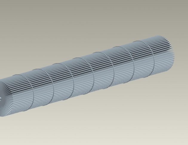
Fan Wheel/ Fan Blade /Fan Impeller of AC
Fan Wheel/Fan Blade 
a)- I clicked on the file and opened the new part and selected the "Revolve sketcher" from the window of pro e software and then I selected the "front datum" for designing the Fan wheel.
b)- I set the horizontal and vertical reference using the sketcher reference line for drawing the fan wheel.
c)- After that I selected the rectangle tool and draw the rectangle on the horizontal referenced line and entered the value 9.8 for the horizontal and value 0.75 for the vertical and accepted the changes.
d)- Then I selected the lower reference along which to revolving the correct dimensioned rectangle to create the wheel like shape.
e)- After that I clicked the “sketcher tool” and then selected the one side of the wheel and draw the cut like shape. And I clicked on the arrow to set the direction inwards towards the wheel and gave it the value equal to length of the wheel i.e. 9.8.
f)- Then I clicked on the “remove material” to remove the material from one side to another side of the fan wheel and clicked on the check icon for the compliance of the features.
Pattering of the Side Cut:
a)- In the “model tree” I clicked right on the side cut “extrude” and then selected the pattern thus a “dialog box” opened and I selected the axis from the direction thus remaining boxes opened and I entered 60 value for the number of cuts in the side box and set the gap 6 for the cuts i.e.- 360/60=6
b)- After all I made the screw posts on the middle of the both sided edges of the fan wheel using the circle giving the diameter 0.01 and set the depth 0.02 and then clicked the arrow to inward the direction and then removed materials and agreed with the features.
c)- Using “revolve sketcher” again I also made 7 square lines giving then gap of 1 from each other, around the fan wheel as shown in the above diagram. Thus we have a complete Fan wheel of split AC.


