WATER LEVEL INDICATOR
I am a student of electrical engineering (Electronics and telecom) and today I am going to share my experience of my first lab project in engineering field.
As you can clearly see from name “Water level indicator” you must think of a simple invention but this device has very vast use in industries.
Basically water level indicator is a device used to indicate the level of water and useful for industries purpose to inform about the different levels of fluid.
Now question is how we can simply make this device at home and use this generic and efficient device for our household.
Now i am going to explain its construction and working in detail.
COMPONENTS REQUIRED:
I. LED (Light Emitting Diode)
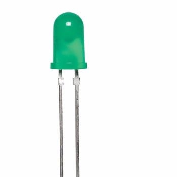
(Photo credit: Google)
II. Transistor (BC548C)
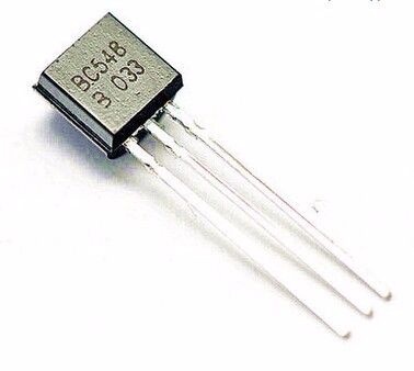
(Photo credit: Google)
III. Connecting Wires
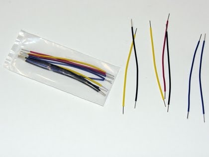
(Photo credit: Electronics.stackexchange.com)
IV. 9 Volts Battery
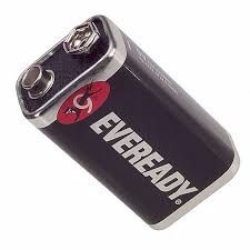
(Photo credit: digikey.com)
V. Vero Board
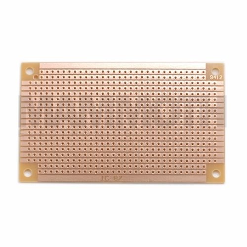
(Photo credit: mammothelectronics.com)
VI. Resistors (330 ohm)
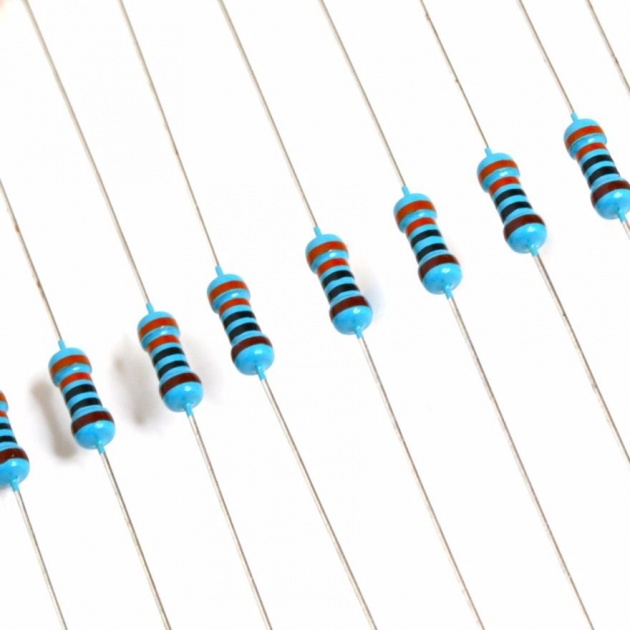
(Photo credit: oddwires.com)
VII. Water Container
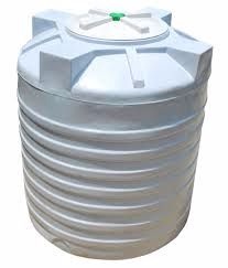
(Photo credit: snapdeal.com)
VIII. Soldering iron and solder
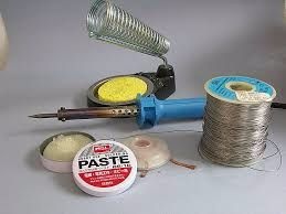
(Photo credit: greger.fr.yuku.com)
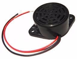
IX. Buzzer
(Photo credit: modmypi.com)
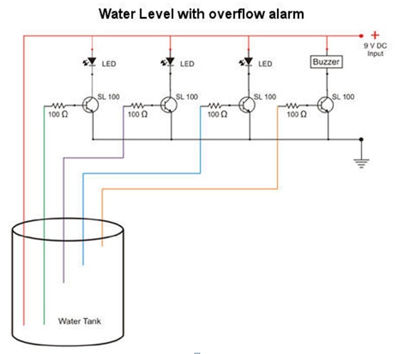
CIRCUIT DIAGRAM:
CONSTRUCTION:
We connected three transistor(bc547) on Vero board and from the collector of each transistor we connected 3 resistors of 3.3k ohm’s. We soldered all three resistors on Vero board. We also soldered a wire and connected this wire with lower surface of water container. We also soldered positive terminal of 9v battery with resistors. Then we connected three LED’s on the emitter of each transistor such that long terminal of Led which is anode is soldered with the emitter of transistor by soldering.
Then we ground the cathode of each leads by taking one wire from the cathode of each led and soldered all three wires in one place on Vero board. We also soldered negative terminal of 9v battery with these wires. Then we soldered 1 wire from base of 1st transistor similarly we soldered another wire with the base of 2nd transistor and similarly from 3rd transistor too. We also soldered a wire from positive terminal of buzzer with the emitter of 3rd transistor.
The wire which we soldered with the base of 1st transistor, we named it level 1 wire and connected it with lower part of water container. The 2nd wire we soldered with base of 2nd transistor, we named it level 2 wires and connected it with middle of water container. The 3rd and last wire which we soldered with base of 3rd transistor, we named it level 3 wires and connected it with upper part of water container.
WORKING:
When water rises and touches level 1 wire in water container 1st LED will glow (i.e. white light).
When water level rises in water container and water reaches level 2 wire 2nd Led will glow (i.e. red light).
When water level rises more and touches the level 3 wire 3rd will glow (i.e. green light) and buzzer also starts sounding.
APPLICATIONS:
I. Automatic Water level Controller can be used in Hotels, Factories, Homes Apartments, Commercial Complexes, Drainage, etc., It can be fixed for single phase motor, Single Phase Submersibles, Three Phase motors.
II. Automatic water level controller will automatically START the pump set as soon as the water level falls below the predetermined level (usually 1/2 tank) and shall SWITCH OFF the pump set as soon as tank is full.
III. Fuel level indicator in vehicles.
IV. Liquid level indicator in the huge containers in the companies.
Hope you like it. Thanks for reading this blog.

